Total: 186 results found.
Page 9 of 10
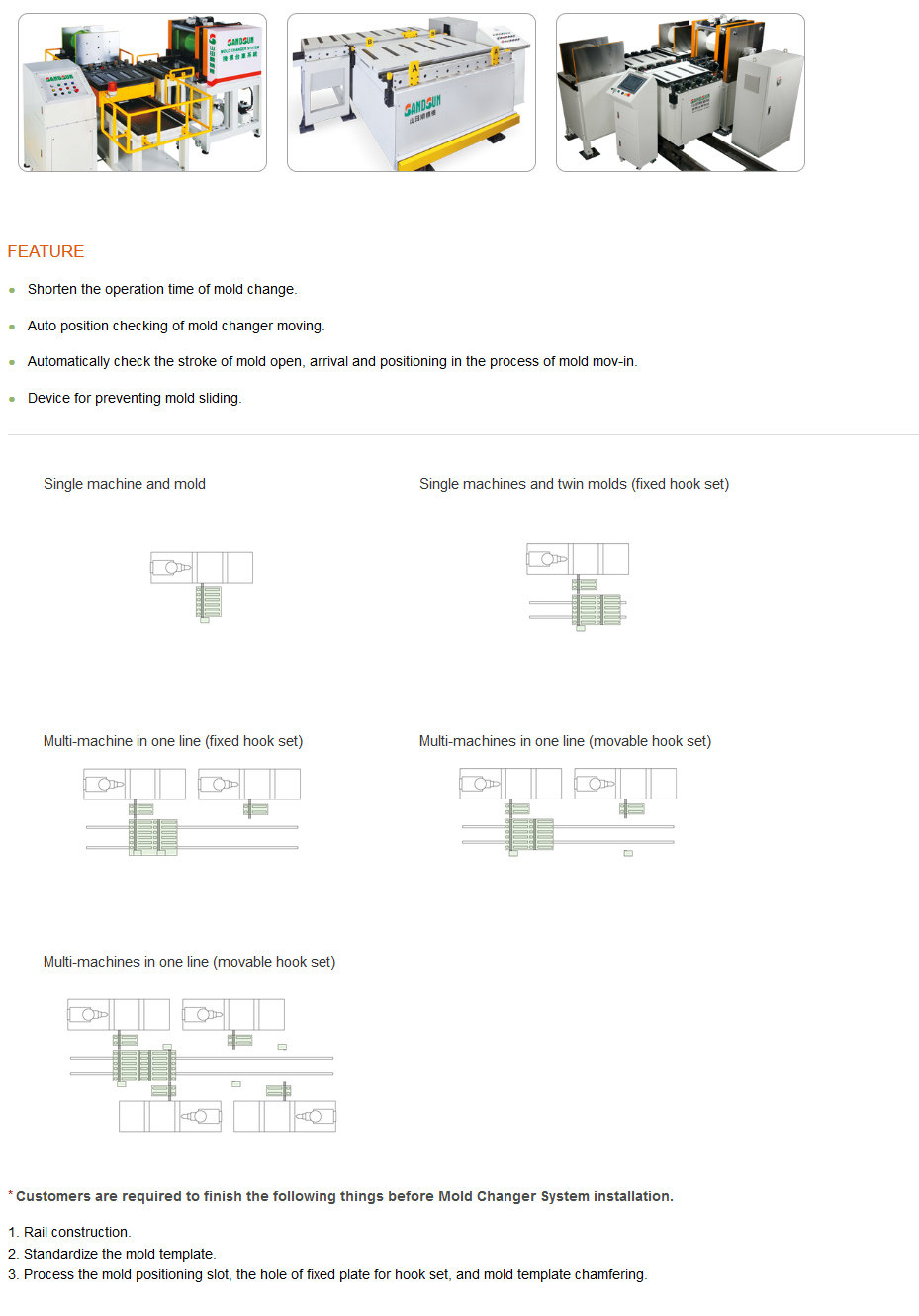
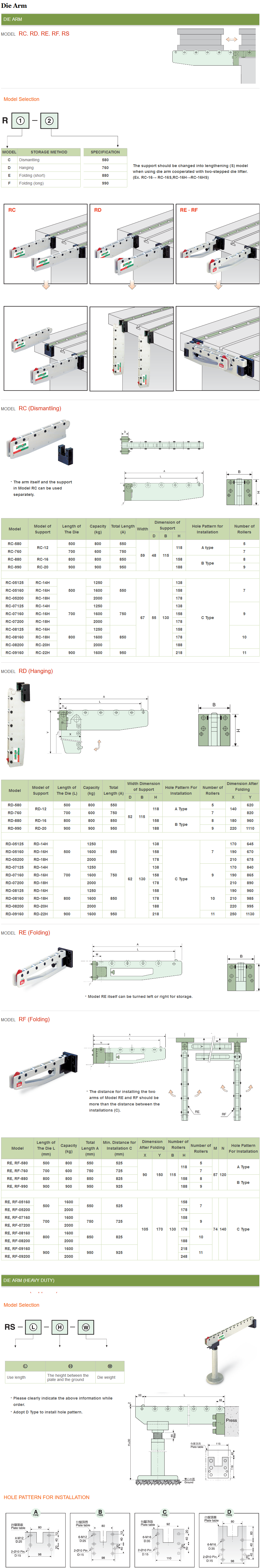
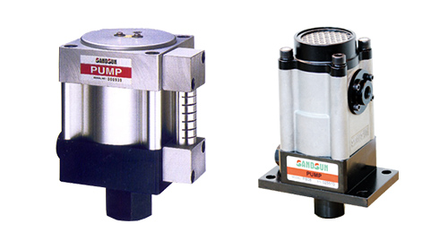
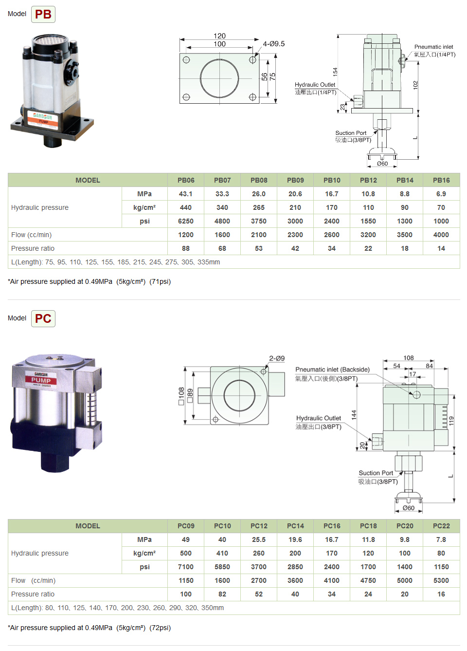
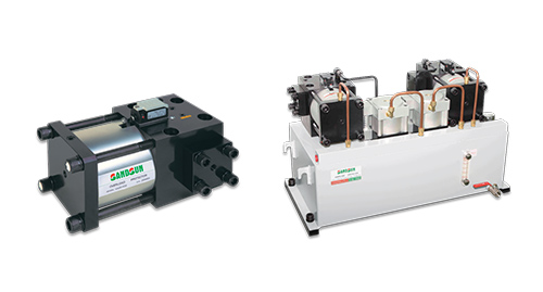
Air Driven Hydraulic Pump Unit 氣動油壓泵浦單元
- The hydraulic pump is driven by air. Once the hydraulic pressure reaches the pressure setting, it stops pumping which is energy saving. Meanwhile, if the working pressure reduces, the pump would supply pressure automatically to keep working pressure continuously.
- The circuit control system is designed with the function of checking and avoiding oil leakage. If pneumatic pressure out, the hydraulic pressure still maintains.
- It is capable of pressure inspection and connecting to machines.
- It is suggested to adopt pump model PC12 when used with clamp model CA&CB-16 or 25
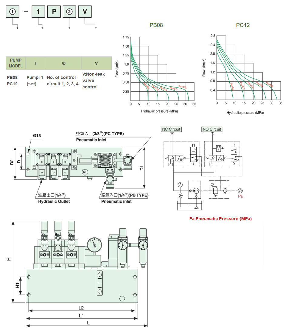
| MODEL | L | L1 | L2 | H | H1 | D | D1 | D2 | Volume |
|---|---|---|---|---|---|---|---|---|---|
| PB08-1P1V | - | 378 | 353 | 367 | 80 | 80 | 235 | - | 6L |
| PB08-1P2V | - | 438 | 413 | 367 | 80 | 80 | 235 | - | 7L |
| PB08-1P3V | - | 498 | 473 | 367 | 80 | 80 | 235 | - | 8L |
| PB08-1P4V | - | 588 | 563 | 367 | 80 | 80 | 235 | - | 10L |
| PC12-1P3V | 560 | - | 473 | 367 | 80 | 80 | - | 166 | 8L |
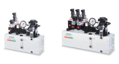
The air combination unit of Model PB08 in the front, and Model PC12 on the right side.
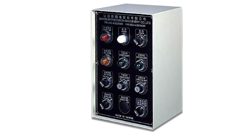
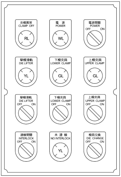
Electronic Control Operation Panel 電控操作箱
Functions:
1.Interlock switch:
(1)"ON"
A. can operate the upper and lower clamps to clamping or unclamping.
B. must to use quick die change system, then the press can be operated.
(2)"OFF"
A. can’t operate the upper and lower clamps to clamping or unclamping
B. no using quick die change system, then the press can be operated.
2.Die change switch:
(1)"ON"
-can operate the upper and lower clamps to unclamping.
(2)"OFF"
-can’t operate the upper and lower clamps to unclamping.
3.Clamp switch: (including upper and lower clamp ):
(1)"ON" - clamping
(2)"OFF" - unclamping
4.Clamp indicator lamp: (including upper and lower clamp ):
When the die was clamping completion by the clamp of the upper or lower clamp and the oil pressure is higher than the setting pressure ( 19.6 Mpa ), the green indicator lamp –light.
5.Die lifter switch:
(1)"ON" - up the die
(2)"OFF" - down the die
6.Clamp off indicator lamp:
(1) Lamp On: ( if the interlock switch "ON", could be the following abnormal conditions )
A. If not all clamps of the upper and lower clamp don’t clamping completion.
B. All clamps are clamping completion, but the hydraulic pressure is lower than 19.6 Mpa.
C. Outer pipe or some oil leakage, cause the hydraulic pressure is lower than 19.6 Mpa.
D. Air supply pressure is too low, to make the hydraulic pressure is lower than 19.6 Mpa.
(2) Lamp Off:
A. When the interlock switch "ON", upper and lower clamp in clamping completely, and upper and lower clamp green indicator light is lamp on.
B. When the interlock switch "OFF".

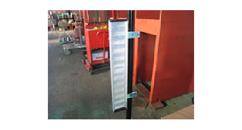
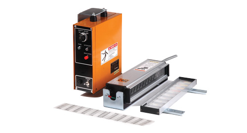
Material Leveler 材料自動整平機
Details
- Practical and economical with simple mechanism.
- High reliability with easy maintenance.
Specifications
| 產品型號 Model |
ML- | ||||||
| 150 | 300 | 400 | 500 | 600 | 700 | 800 | |
| 最大材料寬度 Max. Material Width (mm) |
150 | 300 | 400 | 500 | 600 | 700 | 800 |
| 材料厚度 Material Thickness (mm) |
A:0.5~1.6 B:0.5~3.0 | ||||||
| 整平速度 Straighten Speed (m/min) |
16 | ||||||
| 整平馬達 Straighten Motor (HP) |
1 | 2 | 3 | 5 | |||
| 感應方式 Sensor Type |
接觸式 Touch | ||||||
| 整平滾輪直徑 Straighten Roller Diameter (mm) |
A:∅48*7 B:∅60*7 | ||||||
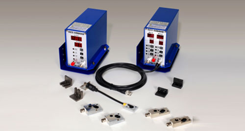
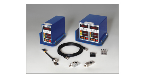
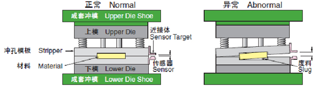
DUCIS Stamping die computerized Slug Detector SD-401/402/601/602/802/804
沖壓模具微電腦下死點檢出裝置
DUCIS SD-401/402
Product Features
SD-401-One basic unit, Single output device (Single Port)
SD-402-One basic unit, Dual output device (Dual Ports)
1.Sensor operation setup distance: Location(A)from 0.8mm to 1.2mm,please press setup switch thereafter 199-0 displayed ,Move the iron
block of the sensor head ,it can be adjusted to 80~120 as operation distance. (Meaning 0.8mm to 1.2mm ) Press setup switch again after set-up process.
2.Operation of monitoring value setup: Accuracy range set up from ±1μm~±99μm,depends on your exact accuracy requirement.
3.While stamping die starts running, the first four times displaying digits meaning the average of the die-height testing.(It will be
re-calculated while stamping machine power off or the sensor line out of the basic unit and re-plug-in).
4.Self-Check functions available.
5.This product provides precision set-up value as 1μm, it is selectable against different accurate toolings.
6.Options available for Error-Carry-On, Missing material (by Electro-Eyes sensor) and Material Jammed (By sensoring Bar)
Specifications:
| Operating Temperature Range | 0~50℃ | Standard Accessories | Sensor、Sensor line 3M、iron block |
|---|---|---|---|
| Weight | SD-401-2.2kg / SD-402- 2.3kg | Length of Sensor | 10 cm |
| Output Contact | Relay Contacts(A..B)250V3A | Length of Join Cable | 3M and 5M 2Models |
| Power Supply | AC85V~250V50/60Hz ±10% | Gap between and Proximity Element | 0.8mm~1.2mm |
| Dimensions | 105W*140H*185D | Maximum Speed | 1200 S.P.M |
DUCIS SD-601/602
Product Features
SD-601-One basic unit, Single output device (Single Port)
SD-602-One basic unit, Dual output device (Dual Ports)
1.Sensor operation setup distance: Location(A) from 0.8mm to 1.2mm,please press MONITOR ON/OFF switch thereafter the red light lights
up.Then press setup switch thereafter “Hi” displayed. Move the iron block of the sensor head, it can be adjusted to 0.8mm~1.2mm as
operation distance.(Meaning 0.8mm to 1.2mm). Press MONITOR ON/OFF switch again after set-up process,the Green light lights up.
2.Operation of monitoring value setup: Accuracy range set up from ±0.5μm~±99.9μm,depends on your exact accuracy requirement.
3.While stamping die starts running, the first six times displaying digits meaning the average of the die-height testing.(It will be re-calculated
while stamping machine power off or the sensor line out of the basic unit and re-plug-in),please press monitor MONITOR ON/OFF
switch thereafter the green light lights up.
4.This product can be choose set up in effective or ineffective.The lights is red when the set up is off.The lights is green when the set up is
on.
5.This product provides precision set-up value as 0.5μm, it is selectable against different accurate toolings.
6.Options available for Error-Carry-On, Missing material (by Electro-Eyes sensor) and Material Jammed (By sensoring Bar).
Specifications
| Operating Temperature Range | 0~50℃ | Standard Accessories | Sensor、Sensor line 3M、iron block |
|---|---|---|---|
| Weight | SD-601-2.2kg / SD-602-4kg | Length of Sensor | 10 cm |
| Output Contact | Relay Contacts(A..B)250V3A | Length of Join Cable | 3M and 5M 2Models |
| Power Supply | AC85V~250V50/60Hz ±10% | Gap between and Proximity Element | 0.8mm~1.2mm |
| Dimensions | 105W*140H*185D | Maximum Speed | 1200 S.P.M |
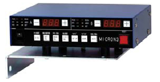
RIKEN MICRON III
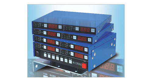
Product Features
1.High Accuracy with 0.1μm resolution.
2.Simultaneously Monitors Rolling Average and Benchmark.
3.Fault Counter Function incorporated.
4.Automatic Sensor Calibration incorporated.
5.Slow Down Detecting Function employed.
6.Corresponds to Servo Press machine(Optional).
7.Various Sensors are provided.
8.Front Porch (One bound) Detection is available.
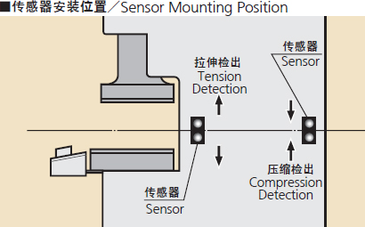
Detection Method
Specifications
| Item | Model | Contents |
|---|---|---|
| Base Unit (2ch) | MIC3-B | Not include sensor |
| Additional Unit (2ch) | MIC3-K | Not include sensor |
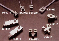
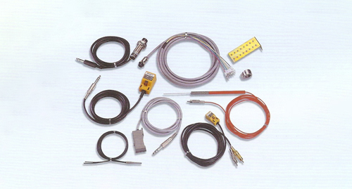
| Sensor | KS-1010 | Standard sensor |
| Junction Cables | 3RC | Cable (3m) |
| 5RC | Cable (5m) | |
| Bracket | JMKS-1 | Sensor Mounting Bracket and target |
| Standard Sensor | Kit Including Sensor(KS-1010),Junction Cable(3RC), Bracket(JMKS-1) | |
| Optional Sensors | See the right sided figure | |
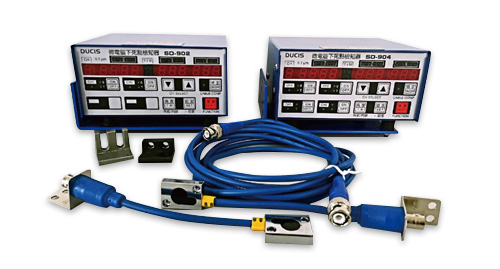
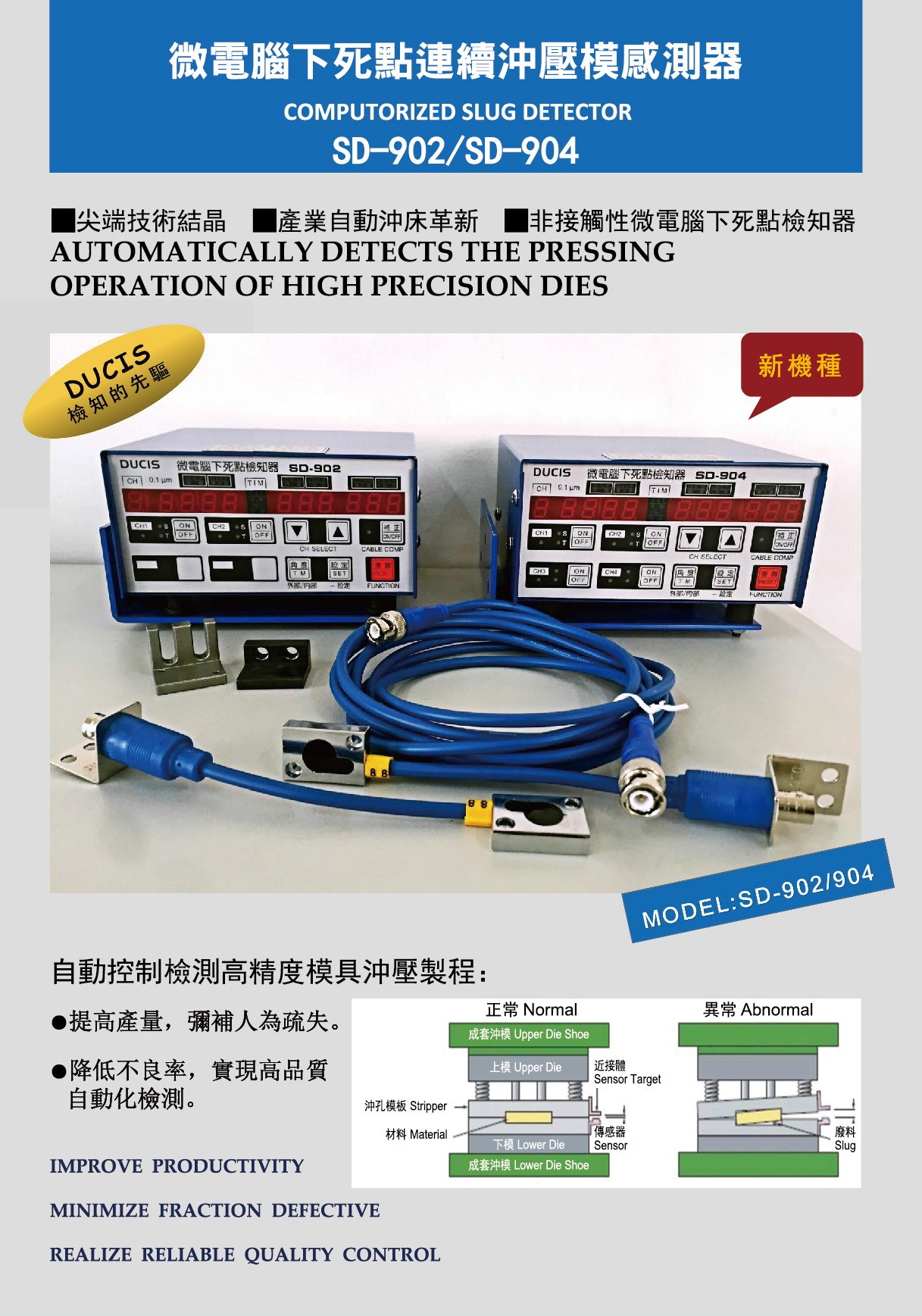
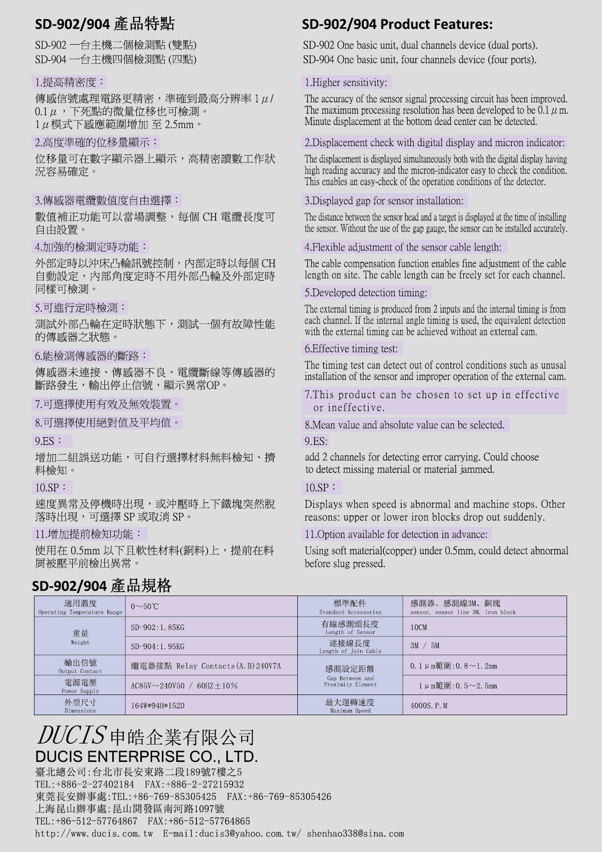
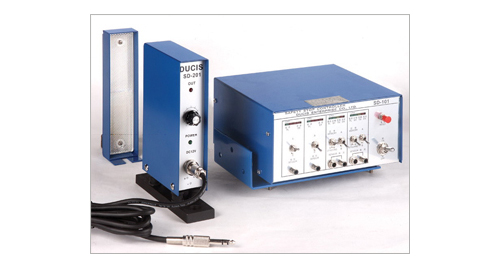
DUCIS SD-802/804(New Product 0.1u)
Product Features:
SD-802 One basic unit, Dual channels device(Dual Ports).
SD-804 One basic unit, Four channels device(Four Ports).

DUCIS-Error-Carrying and Passing Through Inspection Device SD-101/102/201/202
DUCIS SD-101/102/201/202
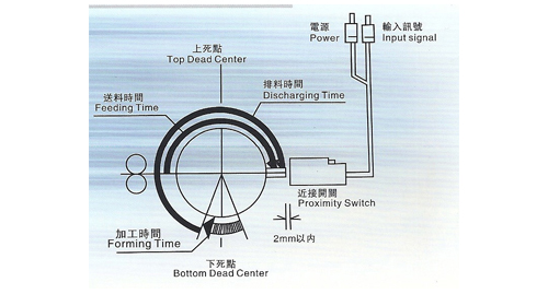
The chart of synchronization signal and angle
NON-CONTACT CHECKING METHOD:
Limit Switch used to do discharge and synchronization check.The chart shows the relation between the input signal time and the angle.
SD-101/102
| “A” Corrugation Extrusion | Detecting Rod: ”ON” Contact Check |
| “B” Feeding Out | Detecting Rod: ”OFF” NON-Contact Check |
| “Synchro” Shortage of feeding Distance of feeding |
Work with the feeding time of the machine to check feeding checking point is fixed at 90° .(TM yellow lamp).The material must be fed at right place before brightening of TM lamp. IF not, the machine stops. |
| “Memory” Discharging workpiece | On every pressing stroke,it must has a workpiece to pass the detecting device(photoelectric,magnetic,micro,proximity switches,etc.)which outputs a checking signal to the controller to store("MY"green lamp). TM lamp brightens and eliminates the memory if NO workpiece passes. The machine stops. |
| Detecting Device | Proximity,photoelectric,infrared detection switch(DC 12V,built-in amplifier),and the detecting rod,micro-switches. |
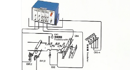
| SD-101 | SD-102 | ||
| CH1-2 | Check corrugation and extrusion of materials (“A”position)check feeding out(“B”position). |
CH1 | Check corrugation and extrusion of materials (“A”position)check feeding out(“B”position). |
| CH3 | Check shortage of feeding, distance of feeding (“Synchro”position) using proximity switch, photoelectric switch. | CH2 | Check the orientation. Using the optical fiber. |
| CH4 | Confirmation of discharging workpieces. Using SD-201/202. | CH3 | Check shortage of feeding, distance of feeding (“Synchro”position) using proximity switch, photoelectric switch. |
| CH4 | Confirmation of discharging workpieces. Using SD-201/202. | ||
Specifications:
| SD-101/102 | SD-201/202 | ||
| Channel | 4.check individually | Checking amplitude | (Infrared detection) SD-201:MAX 150mm SD-202:MAX 100mm |
| Switches | A/B,memory/synchronize | Minimum check | φ2mm(checking distance:0.5M) opacity |
| Response time | “ON”check:3μ,”OFF”check:<300μ | Checking distance | <500mm |
| Power supply | AC85V~250V、50/60Hz±10% | Power supply | DC12V(±10%) |
| Power consumption | <16W | Power consumption | <60mA |
| Output signal | Relay/A/B(220V3A),(110V8A) | Indicating lamp | Green:POWER , Red: GO |
| Delayed time | <10ms | Sensibility | Adjusted by the shape of material and distance |
| Applicable temperature | 0℃~40℃ | Applicable temperature | 0℃~40℃ |
| Input signal | DC12V、detecting device | Response speed | <1ms |
| Standard accessories | SD-101: Detecting rod 2pcs;proximity switch 1set;length of join cable 2pcs SD-102: Detecting rod 4pcs;proximity switch 1set;length of join cable 2pcs |
Length of joint cable | 2.5M |
| Dimensions | 175W*212L*100H | Dimensions | 40W*210L*180H |
| Weight | 2.65kg | Weight | Main unit:1.2kg/Reflective plate :0.3kg |
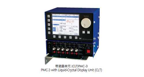
RIKEN PMC-3
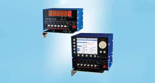
Product Features
1.Easy operation with user friendly design.
2.The expandable design which meets the variety of needs.
3.Enhance the functionality with additional units on demand.
4.Counter unit is easy to see by the large-sized LED display.
5.Large Liquid-Crystal Display Unit (CLT) enables production management.
6.CLT unit employs large color liquid crystal and enables wide range appreciation.
Detection Functions
End-of-Material Detection (CH1)
The device detects the end of feeding material, using a touch sensor, a limit switch, etc. and outputs a stop signal.
Buckling Detection (CH2・CH3)
The device detects buckling when material is caught or bended in the die, using a touch sensor, limit switch, etc., on the material feed side, and outputs a stop signal.
Mis-feed Detection (CH4)
The device checks whether material is fed in proper length during one stroke, using a timing signal, touch sensor, etc., and outputs a stop signal upon detection of mis-feed.
Ejection detection(CH5・CH6)
The device detects ejection of the work using a light curtain sensor, magnetic pass-through sensor. etc., determines the presence of a fault and outputs a stop signal.
Optional Unit
Counter Unit
PMC-CU is an optional counter unit for used with PMC3. With the addition of this unit, not only a six-digit counter can be made use of,but also much more function can be added:
Selection of detection functions
For each channel, a detection function can be selected from make, break, mis-feed and ejection detections.
Reference cam function
(special function for continuous operation)
Use of a reference cam makes it possible to generate two types of arbitrary timing signals.
Switching of sensor input polarity
Switching between sensor inputs can be done for each channel.
SPM Display
Shows SPM during press operation.

Liquid-Crystal Display Unit (CLT)
CLT is an optional Liquid-Crystal Display Unit for used with PMC-3
and it has various and rich functions which are useful for productivity improvement and rationalization.
With adding this unit, anyone can operate and set various functions of PMC-3 interactively.
Model |
Commodities Component |
|||||||
PMC-3-BU |
PMC-3-MU |
PMC-3-CU |
Sensor Kit |
LDS-100 |
LDR-110 |
LDS-200 |
Remark |
|
PMC-3N |
||||||||
PMC-3A |
○ |
─ |
─ |
○ |
─ |
─ |
─ |
|
PMC-3B |
○ |
─ |
─ |
○ |
○ |
─ |
─ |
|
PMC-3R |
○ |
─ |
─ |
○ |
─ |
○ |
─ |
|
PMC-3ML |
○ |
─ |
─ |
○ |
─ |
─ |
○ |
|
| PMC-3N with Counter Unit | ||||||||
PMC-3CA |
○ |
─ |
○ |
○ |
─ |
─ |
─ |
|
PMC-3CB |
○ |
─ |
○ |
○ |
○ |
─ |
─ |
|
PMC-3CR |
○ |
─ |
○ |
○ |
─ |
○ |
─ |
|
PMC-3CL |
○ |
─ |
○ |
○ |
─ |
─ |
○ |
|
| PMC-3N with CLT unit | ||||||||
PMC-3MA |
○ |
○ |
─ |
○ |
─ |
─ |
─ |
|
PMC-3MB |
○ |
○ |
─ |
○ |
○ |
─ |
─ |
|
PMC-3MR |
○ |
○ |
─ |
○ |
─ |
○ |
─ |
|
PMC-3ML |
○ |
○ |
─ |
○ |
─ |
─ |
○ |
|
| Unit only | ||||||||
PMC-3-BU |
○ |
─ |
─ |
─ |
─ |
─ |
─ |
PMC-3N Unit |
PMC-3-MU |
─ |
○ |
─ |
─ |
─ |
─ |
─ |
CLT Unit |
PMC-3-CU |
─ |
─ |
○ |
─ |
─ |
─ |
─ |
Counter Unit |
| Touch Sensor | ||||||||
Sensor Kit |
─ |
─ |
─ |
○ |
─ |
─ |
─ |
Touch Sensor |
| Part Ejection Light Sensor | ||||||||
LDS-100 |
─ |
─ |
─ |
─ |
○ |
─ |
─ |
Direct Projection type, 100mm Height |
LDS-200 |
─ |
─ |
─ |
─ |
─ |
─ |
○ |
Direct Projection type, 200mm Height |
LDR-110 |
─ |
─ |
─ |
─ |
─ |
○ |
─ |
Reflection type, 110mm Height |
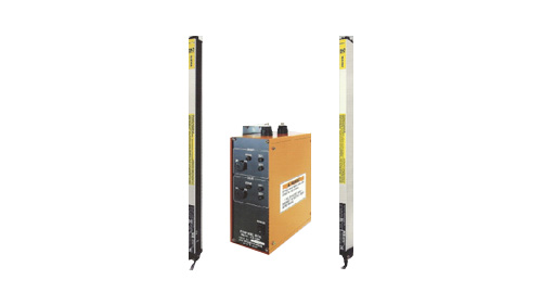
Riken Safety Sensor Device SEII series 理研 光線式-SEII系列 光電保護裝置
- RIKEN Reflection Type-SEII Series
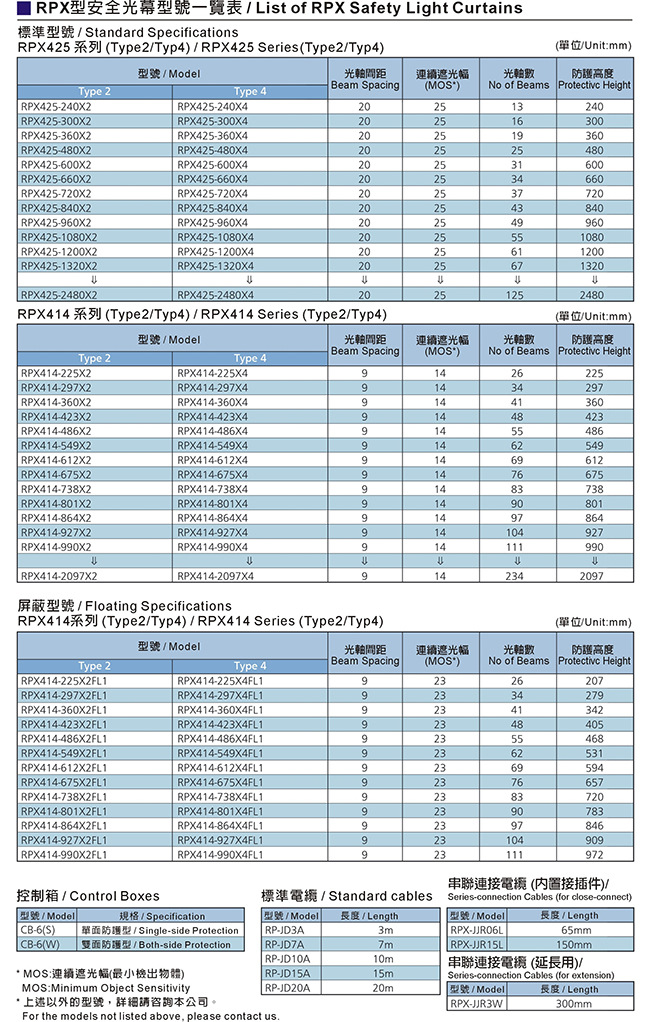
- RIKEN Direct Projection Type-RSL230 Series
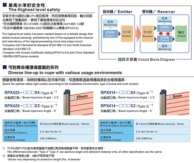
- RIKEN Direct Projection Type-RPZ Series
- RIKEN Direct Projection Type-RPZ Series
RIKEN Reflection Type-SEII Series
Product Features
1.Additional built-in self-check circuit checks electronic circuit automatically to monitor operation safety.
2.Efficient design reduces weight by 50% compared to conventional systems.
3.Negative effects of ambient light are reduced compared to the previous SE model.
4.Energy-saving circuitry reduces power consumption by 50%.
5.Down-sized light sensor allows for an expanded working area.
6. Special filter improves strength against staining and tarnishing.
| Detective distance | Optical axis pitch | Protection height | No. of optical axis | Models |
| 0.4~3M | 40mm | 200mm | 6 | SEII-24 |
| 280mm | 8 | SEII-32 | ||
| 360mm | 10 | SEII-40 | ||
| 440mm | 12 | SEII-48 | ||
Product Features
1. LED indicator bar for easy operation.
2. Variety of built-in safety functions in the sensor unit.
3. Type 4 safety light curtain conforming to IEC and EN.
4. Immediate emergency stop.Achieved the highest degree of safety.
5. Complete failsafe design -the self-diagnosis function turns off the output of emission in case of malfunction.
6. Safety design backed by advanced technology. The highest-level safety design engineering and FMEA.
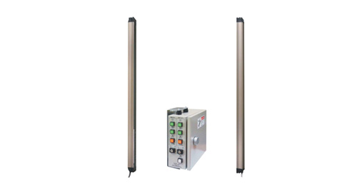
RIKEN Direct Projection Type-RSL230 Series
Product Features
1. 20mm pitch optical axes accurately cover the protection area without fail.
2. 8~100 optical axes types in the unit of every 4-optical-axes are available and selectable from 140~1,980mm
length variation.
3. Light and slim design requires minimum installation space and thus allows large workspace.
4. When an error arises, its cause is indicated with LED flashing patterns.
5. Employed pre-wired feature realizes simple cable connection and easy installation.
6. Employed direct projection type safety system makes it possible to adjust optical axes easily.
7.Control box is selectable from one-side and both-sides types, The both-sides type enables to control 2 pairs
of emitters and receivers simultaneously.
Kinds
| Detective distance | Optical axis pitch | Protection height | NO. of optical axis | Models | Models | ||
|---|---|---|---|---|---|---|---|
| 0.2~6m | 20mm | 140mm | 8 | RSL230-140(S) | RSL230-140(W) | ||
| 220mm | 12 | RSL230-220(S) | RSL230-220(W) | ||||
| 300mm | 16 | RSL230-300(S) | RSL230-300(W) | ||||
| 380mm | 20 | RSL230-380(S) | RSL230-380(W) | ||||
| 460mm | 24 | RSL230-460(S) | RSL230-460(W) | ||||
| 540mm | 28 | RSL230-540(S) | RSL230-540(W) | ||||
| 620mm | 32 | RSL230-620(S) | RSL230-620(W) | ||||
| 700mm | 36 | RSL230-700(S) | RSL230-700(W) | ||||
| 780mm | 40 | RSL230-780(S) | RSL230-780(W) | ||||
| 860mm | 44 | RSL230-860(S) | RSL230-860(W) | ||||
| 940mm | 48 | RSL230-940(S) | RSL230-940(W) | ||||
| 1020mm | 52 | RSL230-1020(S) | RSL230-1020(W) | ||||
| 1100mm | 56 | RSL230-1100(S) | RSL230-1100(W) | ||||
| 1180mm | 60 | RSL230-1180(S) | RSL230-1180(W) | ||||
| 1260mm | 64 | RSL230-1260(S) | RSL230-1260(W) | ||||
RIKEN Direct Projection Type-RPZ Series
Product Features
1. Failsafe design for the highest level safety.
2.Diverse line-up to cope with various usage environments.
3. Series connection function and error display function equipped.
4. Simple to adjust beams.
5. Mutual interference prevention.
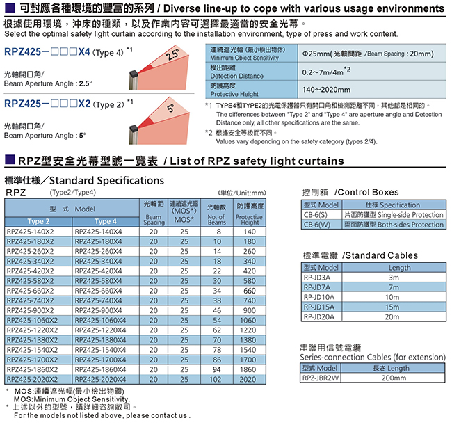
RIKEN Direct Projection Type-RPZ Series

Product Features
1. Failsafe design for the highest level safety.
2.Diverse line-up to cope with various usage environments.
3. Mutual interference prevention.
4. Various blanking functions equipped.
5. Indication of light-reception level for simple beam alignment.
6. Mounting brackets that significantly reduce influence of vibration.
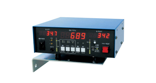
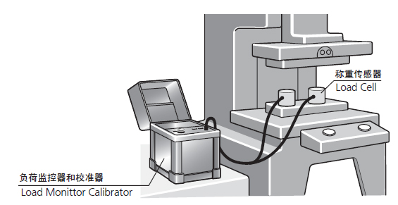
RIKEN Load Monitoring System PLA-2N / PLA-4N沖壓機負荷監視裝置
RIKEN Load Monitoring System PLA-2N
Product Features
1.Easy to know the balance of loads applied to the left and right sides of the press, and to know improper balance,
load center, etc., it facilitates die maintenance and quality control.
2.As a overload protector, it prevents from the damage of the dies by detecting double hits, mis-feed, change of
material thickness etc., and estimates die regrinding intervals.
3.By knowing the suitable load for products, the selection of the press is facilitated.
4.The detector can be used to simultaneously set absolute value comparison (set value of upper/lower limits) and
comparison with the value of the previous time.
5.The digital LED display is easy to read, and the bar display shows the left load and the right load in percentage.
The PLA-2N has the function of detecting the press load with a strain gauge. It displays the accurate load during press processing, and output stop signals and stops a press machine immediately when abnormality is detected. Monitoring cannot be ignored when there are eccentric loads for each stroke, and furthermore, load monitoring extends the life of dies, prevents friction and wear of presses, also promotes quality control and rationalization.
Description of Components
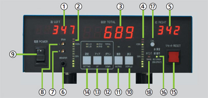
- Left Load Display
- Left Bar Display
- Total Load Display
- Right Bar Display
- Right Load Display
- Waveform Output(Analog Signal Output)
- Right Sensitivity Control
- Left Sensitivity Control
- Power Switch
- Display Change Key
- Muting Key
- Down Key(used to change settings)
- Up Key(used to change settings)
- Setting Key(used to change various settings)
- Reset Key(pressing this key cancels the emergency condition)
- Operation Lamp(lighting in red means thata fault signal is being output)
- CAL Switch(to be pushed when viewing sensitivity settings)
- Timing LampCalibration
When the sensors are left as installed on and wires to the press, the tonnage indication is random and has no significance. Therefore, it is necessary to calibrate the amplification factor of the unit so as to indicate the accurate tonnage.
RIKEN Load Monitoring System PLA-4N
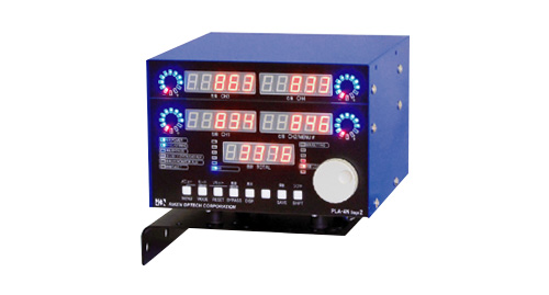
Product Feature
1.Suited for crank type and servo type press machines.
2.Responds to static load.
3.Capable of selecting a method of obtaining the total load (total of Maximum values with consideration to
eccentricity) according to work piece.
4. Provided with an output function for press machine protection (overload otherwise known as capacity alarm).
5.Provided with a function of inputting the number of usable strain sensors (1ch~4ch).
6.Provided with an automatic zero point compensation function.
7.Adopts a digital sensitivity setting method.
8.Adopt a 5-digit display.
9.Provided with an LED level meter display function.
10.Higher visibility by use of blue LEDs.
11.Better operability by adoption of dial type setting.
Detecting Method
The PLA-4N Stage 2 has the function of detecting the press load with a strain gauge. It displays the accurate load during press processing, and output stop signals and stops a press machine immediately when abnormality is detected. Monitoring cannot be ignored when there are eccentric loads for each stroke.

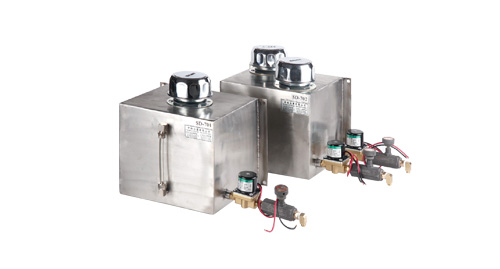
DUCIS Stainless steel with electromagnetic valve automatic lubricant feeder SD701/702
申皓 不鏽鋼附電磁閥自動給油器
DUCIS SD-701/702
Specifications
SD-701 Single port (one output lubricant nozzle, one electromagnetic valve)
SD-702 Dual ports (two output lubricant nozzle, two electromagnetic valves)
Product Features
1.Lubricant fed by the press machine simultaneously. The lubricant stop feeding automatically when the press
machine stop running. The lubricant feeder starts automatically when the press machine re-start.
2.Save the lubricant a lot.
3.It's not necessary to adjust the quantity of lubricant feeding,because of the electromagnetic valve device helps
to auto-control the lubricant.
4.Prevent the corrosive lubricant, because of using the stainless steel of lubricant tank.
5.SD-702(Dual Ports)is suitable to use in the larger press machine.